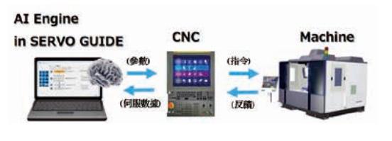
In response to global energy-saving and carbon reduction ESG issues, FANUC has launched the latest machine adjustment tool with AI servo adjustment capabilities. Utilizing SERVER GUIDE PLUS, advanced servo adjustments can be achieved through AI, improving machining performance. The adjustment functions include: 1) AI automatic adjustment of basic servo functions (gain/filter adjustment); 2) AI feedforward control function; 3) AICC acceleration and deceleration adjustment function.
Below is a brief introduction to these three functions:
unction Description: AI servo adjustment can continuously execute the following three adjustments in one operation.
| Adjustment Items |
Reorganization Purpose |
Remark |
1. AI Gain/Filter
|
Enhance response performance |
X
|
2. AI Feedforward/ General Feedforward
| Reduce vibration and improve machining accuracy | Requires optional controller function; without the option, only speed feedforward value can be adjusted. Choice of whether to use a hardware accelerometer is available. |
| 3. AICC Acceleration and Deceleration | Reduce machining time | Must be used with a hardware accelerometer |
Software Requirements: SERVO GUIDE (requires additional optional function) VER11.90 or above / SERVO GUIDE PLUS VER 1.0 or above
1. AI Gain/Filter Adjustment Process
- Adjustment condition settings are divided into: Standard, Emphasize Responsiveness, Emphasize Stability, and Custom Conditions. Generally, Standard is selected as the adjustment option.
- Parameter confirmation/adjustment includes : (1) Related to HRV3 (improve current loop response performance, current gain rate in high-speed HRV). (2) Related to speed gain (servo HRV control (speed loop optimization function), total inertia of the drive system (%), speed loop PI control, high-speed processing function of speed loop proportional item, use high-speed HRV current control during cutting feed, speed loop gain switching during cutting/rapid feed, variable proportional gain during stop (stop judgment level)). (3) Related to the filter (torque filter coefficient (cutting/rapid feed), invalid torque filter coefficient, suppress filter 1~5 (center frequency (Hz), bandwidth (Hz), attenuation (%)), second-order low-pass filter cutoff frequency). (4) Related to gain (load inertia ratio %, speed loop gain rate in high-speed HRV (%), speed loop gain rate during cutting (%)).
- Basic vibration setting (external disturbance input gain, start (end) frequency, frequency characteristics during measurement movement, measurement feed speed); detailed settings (reduce torque limit, lower over-speed alarm detection limit, increase position error limit during stop, position gain is 10%, disable speed loop gain reduction function during stop, disable abnormal load detection, disable servo excessive error, disable high-speed processing function of proportional item during stop).
- Generate and confirm the test program: determine the position of the vibration program, select mechanical or absolute coordinates, and fill in relevant positions (upper, middle, lower travel or left, middle, right travel or front, middle, back travel). Adjust the number of vibrations and select single-axis or multi-axis matrix measurement, with up to 50 measurement points.
- After the test run to confirm the program operation without machine interference, start automatic adjustment.
- After automatic adjustment, compare parameters before and after adjustment:
| Parameters |
Before adjustment |
After adjustment | Parameters | Before adjustment | After adjustment |
Load inertia ratio |
384 |
542 | Filter 2 - center frequency (HZ) | 180 | 1128 |
HRV speed gain rate (%) | 350 | 138 | Filter 2 - bandwidth (HZ) | 30 | 949 |
Speed gain rate during cutting (%) | 150 | 100 | Filter 2 - attenuation (%) | 60 | 21 |
Filter 1 - center frequency (HZ) | 400 | 369 | Filter 3 - center frequency (HZ) | x | 2689 |
Filter 1 - bandwidth (HZ) | 200 | 365 | Filter 3 - bandwidth (HZ) | x | 702 |
Filter 1 - attenuation (%) | 15 | 2 | Filter 3 - attenuation (%) | x | 10 |
2. General Feedforward Adjustment Process
- Adjustment condition settings are divided into: General Feedforward and AI Feedforward (requires function). This section introduces General Feedforward.
- Parameter confirmation/adjustment for General Feedforward: activate feedforward function, feedforward during cutting/rapid feed is effective, default value for feedforward timing adjustment is effective, integral at low speed is ineffective, position (speed) feedforward coefficient, feedforward timing adjustment coefficient.
- Generate and confirm the test program: determine the position and speed of the test program, select mechanical or absolute coordinates, set magnification to 100%, adjust the number of times, run the test program, and start automatic adjustment.
- After automatic adjustment, compare parameters before and after adjustment (single-axis adjustment):
| Parameters |
Before adjustment |
After adjustment |
Feedforward Coefficient during Cutting |
9950 |
10000 |
Speed Feedforward Coefficient during Cutting | 100 | 410 |
3. AICC Acceleration and Deceleration Adjustment Process
- Parameters for AICC acceleration and deceleration adjustment include:
(1) System parameters (type of acceleration/deceleration after interpolation (bell-shaped)/(linear), lower limit speed (%) for deceleration function of acceleration under arc/AI contour control interpolation, proportion of acceleration control change time).
(2) Axis parameters (allowable acceleration change amount [mm/sec²], allowable acceleration change amount (linear interpolation) [mm/sec²], time constant for acceleration/deceleration after second interpolation (cutting feed) [msec]).
(3) AI contour control parameters (maximum allowable acceleration for each axis before interpolation [mm/sec²], allowable acceleration for each axis during deceleration function of acceleration under arc interpolation [mm/sec²], time constant for acceleration/deceleration after interpolation under cutting feed [msec], allowable speed difference determined by speed difference based on corner [mm/min], change time for bell-shaped acceleration/deceleration before interpolation [msec]). - Set three-stage measurement (SETTING 1~3), confirm program running position, and run the program completely at 100% feed rate.
- Allowable error settings include: shape error, position deviation, and vibration error, which are reference values for the measurement program and setting errors, aiming to minimize machining time.
- Set the number of learning times: generally set to 240 times, start automatic adjustment.
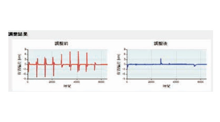
- After automatic adjustment, analyze the results:
(1) Without changing the overall loop's three-stage mode (SETTING 3), machining time was shortened by about 0.2 seconds, improving machining efficiency.
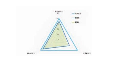
(2) Shape error change: three-axis shape adjustment improved by more than 2 μm compared to before adjustment.
(3) Position deviation change: three-axis position adjustment improved by 0.3 μm compared to before adjustment.
(4) Vibration error change: three-axis vibration adjustment improved surface quality by 0.013 μm compared to before adjustment.
|
Using Sensors / Allowable Error |
|
Vibration Data |
Accelerometer |
Shape Error (right-angle corner) 【µm】 | 80.0000 |
| Shape Error (arc twist) 【µm】 | 40.0000 |
|
Position Deviation 【µm】
| 5.0000 |
| Vibration Error 【μm】 |
0.1000
|
|
F10000
|
Before adjustment |
調整後
|
| Machining Time (seconds) |
18.3
|
18.1
|
|
|
|
|
|
Shape Error µm
|
|
|
|
|
|
|
|
Position Deviation µm
|
|
|
|
Vibration Error µm
|
|
|
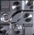
Actual Cutting Verification :
The in-plant GP1 model's actual cutting is displayed separately with and without AI adjustment methods in the illustrations.
Items |
Without AI |
Items Without AI With AI |
|
Nine-Grid Comparison |
 |
 |
|
R-Angle Smoothness |  |  |
|
Machining Time |
31 minutes 15 seconds (1875 seconds)
|
30 minutes 13 seconds (1813 seconds) |
※ Machining efficiency saved 62 seconds (about 3%)
Conclusion
AI servo adjustment uses machine learning to find the best servo parameters by repeatedly collecting data with the AI engine. It can suppress machine vibration, improve servo response, and shorten machining time without complex processes and professional personnel. Currently, SERVER GUIDE is used for manual machine adjustments during new machine project assembly or handling customer complaint cases of mold machining loop anomalies. Among the many parameters of FANUC controllers, sometimes the optimal parameters for the machine cannot be adjusted, causing project delays and customer machining products to be incomplete. This tool, AI servo adjustment, fits this need, though data still needs to be collected for some customer complaint cases, and there are some operational issues FANUC is improving. After improvements, it should speed up resolving customer issues and improve new machine quality.