I. Preface
With the advancement of industrial technology, machine tools must meet diverse customer requirements for workpiece variety and various production conditions. Consequently, the demand for machine tool stability continues to grow. Whether influenced by internal mechanical components or external environmental factors, machining accuracy must be controlled within a specific range to meet manufacturing requirements.
Approximately 40% to 70% of machining errors in machine tools are caused by thermal displacement. During the machining process, heat generated by various components affects the final accuracy through thermal transfer. Therefore, high-precision machine tools are often required to be installed in temperature-controlled facilities to minimize structural deformation and accuracy errors caused by environmental temperature fluctuations.
Long-term machining stability is a key factor for customers. Machine tool manufacturers must understand the correlation between temperature changes and thermal displacement to evaluate machining accuracy under thermal deformation. Internal heat primarily originates from machine operation and the cutting process. Heat sources during operation include motors, bearings, and servo feed systems; heat during cutting is generated by the relative motion between the tool and the workpiece, as well as chip friction. These heat sources change the temperature across the machine via conduction, convection, or radiation, causing structural expansion and contraction. This alters the relative position between the workpiece and the tool, resulting in machining errors. Because thermal deformation has a significant impact on accuracy, a primary focus of machine tool technology development is the effective control of thermal displacement to enhance stability.
Victor Taichung (台中精機) has developed the "Lathe Thermal Displacement Compensation STD (Standard Version)"—an intelligent functional technology specifically for CNC lathes. By considering the heat generation and thermal transfer behavior of all machine components, a comprehensive structural thermal displacement compensation equation was established. This system compensates for structural displacement through axial movement. This not only reduces the frequency of manual offsets required by operators but also effectively improves machine accuracy stability and overall efficiency.
二、車床熱變位補償STD 標準版機能
說明
車床熱變位補償STD 標準版機能針對廠內CNC 車床以電腦有限元素分析(FEM) 軟體模擬計算( 圖1),並搭配多組實機長時間熱變位量測數據與加工工件尺寸變化圖( 圖2)確認整機結構隨時間變化之熱變位方向與趨勢。
圖1、電腦有限元素分析之整機結構熱變位結果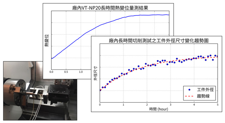
圖2、廠內CNC 車床長時間熱變位量測與切削測試結果
車床熱變位與切削工件尺寸變化結果如圖2 所示,結果顯示熱變位量測結果與外徑尺寸變化趨勢相近,說明刀具與工件間相對變位趨勢為兩者逐漸遠離,且可區分為暫態尺寸變化之第一階段 ( 前3 小時) 與穩態尺寸變化之第二階段 (3 小時後);第一階段主要為機台各部件,包含主軸、軸向等運動件發熱變形之暫態短時變位影響,使加工精度變化較劇烈;第二階段則受整機結構受熱傳遞緩慢與外部環境熱源之結構基底變形影響。
熱變位補償STD 標準版依上述電腦模擬、實機量測與切削測驗等結果彙整建立整機熱變位方程式,以不需額外安裝感測元件方式以估算刀具與工件之相對變位量,再將其反向作為機能補償值輸入CNC 控制器驅動對應軸向移動進行補償以維持加工精度。補償模式上,暫態尺寸變化大之第一階段採短時補償控制模式,短時間頻繁補償維持工件精度;而穩態尺寸變化之第二階段之補償頻率較低,以漸進緩慢補償結構所產生之熱變形影響。廠內車床測試有無熱變位補償STD 機能對工件外徑尺寸變化之影響,結果如圖3 所示:無熱變位補償STD 標準版機能之外徑尺寸隨時間逐漸增大,而開啟機能後能有效將工件尺寸控制在一定範圍,有效提高加工精度穩定性。
圖3、廠內車床驗證有無熱變位補償STD 標準版結果比較
三、客戶端應用案例
廠內實測確認熱變位補償STD 標準版機能之加工精度與穩定性後,進行客戶端各式加工樣態測試驗證,外徑加工之工件尺寸變化結果如圖4 所示,其結果與廠內測試結果相近,無機能案例之工件外徑尺寸隨時間逐漸變大;而開啟機能則能長時間將外徑尺寸控制在一定範圍內,說明車床熱變位補償STD 標準版可有效補償CNC 車床整機熱變位,且維持機台長時間之加工精度穩定性。
圖4、客戶端實測驗證有無熱變位補償STD 標準版結果比較
四、結論
台中精機具備專業研發技術團隊,輔以電腦模擬與精密量測設備持續開發智慧化技術,目標提升機台長時間加工精度之穩定性,希望藉此“車床熱變位補償STD 標準版”機能研究與應用,達到降低操作人員補正頻率,進而提高客戶整體加工效率、產品品質與產量之價值。
CNC Lathe Thermal Displacement Compensation STD (Standard Version)
Functional Introduction and Practical Applications
2026/04/14